Electromechanical Linear Actuator’s Working Principle
1.0 Electromechanical Actuators
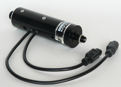
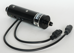
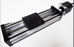
Electromechanical actuators are designed as mechanical actuators only that the lead nut is part of the motor which replaces the control knob. The lead screw is fixed and does not rotate making the lead nut to be the only moving part rotated by the motor. The lead screw can extend outbound or retract inwards.
2.0 Simplified Design
The motor motion is mechanically converted to linear displacement. The designs of linear actuators, however differ depending on the manufacturers who use a wide range of proprietary methods in the designs. In most designs, the lead screw and the nut are incorporated while in some deigns a ball screw and a ball nut are used. There are designs where the screw is connected to the motor directly or by a number of gears.
The core purpose of the gears in such connections is to transmit a low power motion but at a high RPM through gears to magnify its torque to be able to manage the weight exerted on the screw. This prevents engaging the motor directly to a heavy load. In this concept, linear actuator speed is compromised for the purpose of attaining a favorable actuator thrust. As the nut is prevented from moving with the screw head, the non-rotating part is forced to interlock with the actuator.
3.0 Principle
The basic principle of operation in most of electromechanical actuators (see more on the actuators store) is based on the inclined plane concept. The threads of the lead screw are used as a ramp that transforms a small rotational force by magnifying it over a long distance to enable a large load to be moved over a short distance.
4.0 Variations
There are many modifications that have been made from the original concept and design of electromechanical actuators. The main focus is to provide higher mechanical efficiency, create more speed and increase load capacity. Some improvements are also influenced by the need for actuator miniaturization.
Most designs of electromechanical are made of a lead screw and a lead nut. There are others that have adopted the use of a ball screw and a ball nut. In the two makes, the motor can be connected to the screw or the screw is physically connected to the control knob that is operated manually. These connections can be done directly to the motor or by using a series of motors.
There are designs that use worm gears where a small built in dimension provides effective greater travel length. A common design is the traveling screw actuator where the lead screw passes through the motor. In this design, the motor is moved up and down while the lead screw remains fixed. The motor remains the only rotating parts. There are designs which have multiple starts which are alternating threads on the same shaft. These starts on the lead screw provide a higher adjustment capability between the starts and the nut thread area of contact. This influences the extension speed and load capacity of the threads. The lead screw is responsible for determining the direction of motion of the nut. Linear displacement can be attained by connecting linkages to the nut.
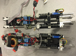
There are many types of motors that can be used in the electromechanical linear actuator systems. The most common ones are the DC brush, stepper, DC brushless or the induction motors. Electromechanical actuators are commonly used in mechatronic applications such as robotics, movable optical and laser machines and X-Y tables fitted with fine resolution in microns. In motor vehicles, the same concept is used in car door windows.


